
Polarisation Voltage Generator PCBs
Board reference code PVGL and PVGS
Page about the polarisation voltage generator boards
Documentation in progress - in the meantime ask me if you have questions
There are two version of the board "long" designed to fit in a BM700/800 body, and "short", designed to fit next to the transformer in a mini U87 body when used with my CFT or HFT boards.
email me at parenthetical at this domain
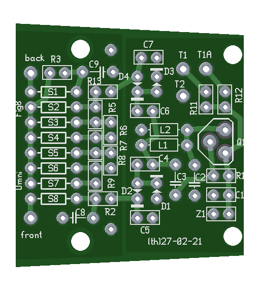
Long version (PVGL)
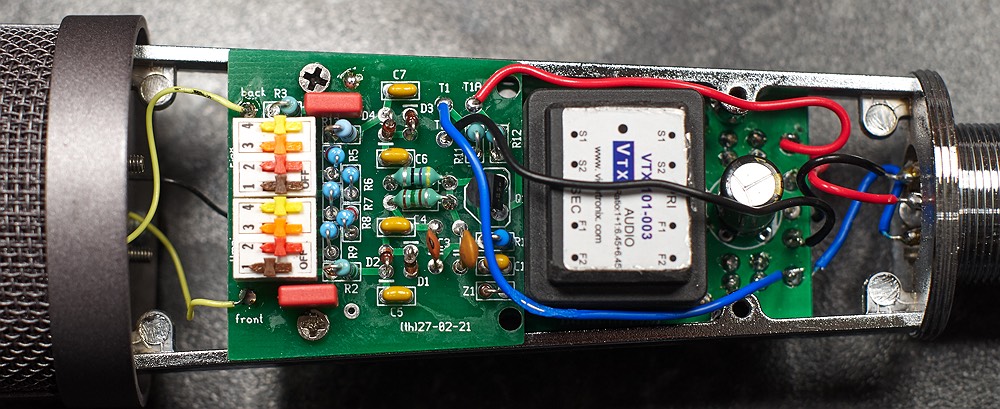
This board has a dual polarisation voltage generator on a board designed for cheap donor mics the BM700 and BM800.
Designed to generate +/-60v although the voltage can be varied somewhat.
Dip switches allow pattern selection for dual diaphragm capsules.
Output voltage can be set by varying the value of Z1. A 9.1V zener gives about +/-60v
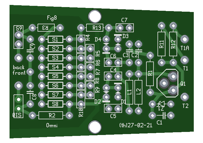
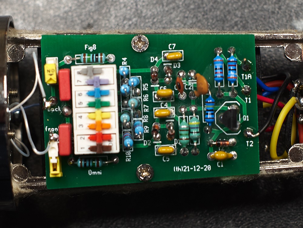
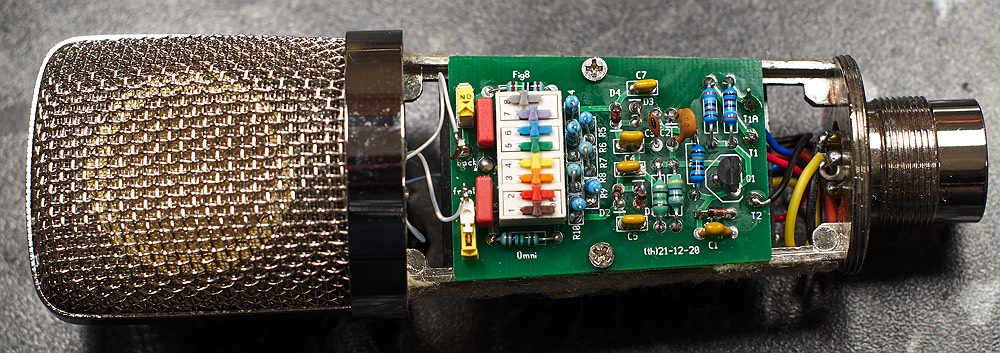
The photos show an earlier version of the board - without S10 or R13. In the pics S10 has been added afterwards. Current boards have S10 properly mounted on the board.
Short version PVGS
Circuit description. (work in progress)
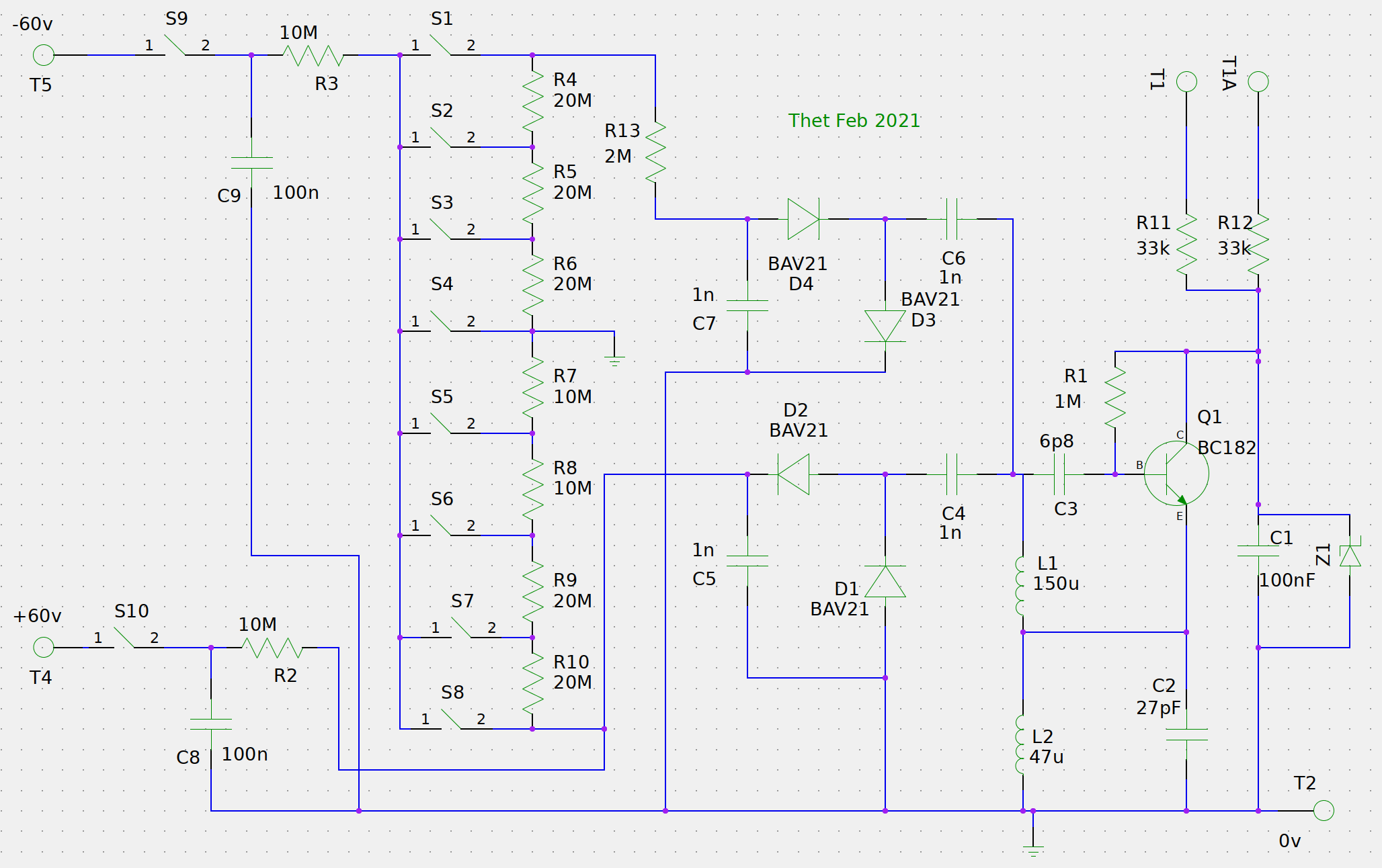
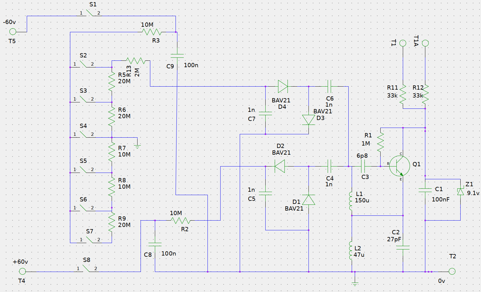
Both boards use the same basic circuit. A low DC voltage is created using C1 and Z1, fed from the XLR pins through R11 and R12. This feeds a high frequency oscillator running at a few Mhz (Q1, C2, R1, C3, L1, L2). This high frequency signal is rectified and filtered to create positive (C4, D1, D2 C5) and negative (C6, D3, D4, C7) voltages. The output voltage is controlled by the input voltage as set by Z1. A 9.1v zener gives around plus and minus 60v output. A higher voltage zener will produce a higher voltage output. If you increase the value of Z1 to get higher voltages R11/R12 may need to be reduced in value to allow enough current through.
You can't measure these voltages accurately with a standard multimeter with a 10Meg input impedance because the output impedance of the voltage generator is so high that even the 10M load of the meter will drag down the voltage. To get a more accurate voltage reading, put a 100Meg resistor in series with the meter to raise the input impedance to 110Meg, then multiply the resulting reading by 11.
To simply test if it is working, you can test the voltage at the join of D2 and C5, if this reads betwen 30v and 50v the circuit is likely OK. Then to get an accurate reading do the above trick with the 100M resistor.
On the long board the positive output is filtered (R2, C8) and fed to T4 via a switch. T5 however is fed from a voltage divider formed by resistors R4-R10, and switches S1-S8; as a result T5 can be set to either +60v, -60v or 6 inbetween values, including 0v.
The purpose of this is to allow multipattern switching for dual diaphragm capsules using the onboard dip switches to select omni, figure 8, or 6 settings in between including cardioid. In this setup the signal is taken from the backplate of the capsule. The front diaphragm is connected to T4 and the back diaphragm to T5.
IMPORTANT - Only one of the dip switches should be engaged at any time.
Long board polar patterns
- S1 on = Figure 8
- S2 on = Hypercardioid
- S3 on = Supercardioid
- S4 on = Cardioid
- S5 on = Wide cardiod
- S6 on = Very wide cardioid
- S7 on = Sub omni
- S7 on = Omni
- S9 off (S10 on) = Cardioid with higher level, as only one diaphragm is connected, eliminating capacitative losses from the second diaphragm.
S10 can be replaced with a wire link if desired. S10 is only useful if you want to make a dual diaphragm mic use the back diaphragm in cardioid mode, (ie S9 on, S10 off, S8 on). This is useful for testing if both sides of a dual capsule sound the same.
This is all a bit complex.The board can also be used in simpler ways:
If you only want the three standard patterns of cardioid, fig8, and omni then you can fit only S1 and S8. and omit S2-S7, and omit R4-R10.
If you have a single side cardioid-only capsule then you can omit ALL the switches, omit R4-R10, put a wire link in place of S10, and omit the negative voltage generator parts (D3, D4, C6, C7, R13).
On the short board the same principle applies, but there are two fewer switches - S1 takes the place of S9, S8 takes the place of S10, and the voltage divder has fewer positions since it now consists of 6 switches rather than 8
Short board polar patterns
- S2 on = Figure 8
- S3 on = Hypercardioid
- S4 on = Cardioid
- S5 on = Wide cardiod
- S6 on = Very wide cardioid
- S7 on = Omni
- S1 off (S8 on) = Cardioid with higher level, as only one diaphragm is connected, eliminating capacitative losses from the second diaphragm.
Part choices
The dip switches should be rated 100v, these can be hard to find. 50v rated is much more common. Given the negligible current it may be that 50v switches will work but I haven't tried it.
C8 and C9 should be high quality C0G or film caps.
All resistors should be metal film for low noise, especially the 10M and 20M ones.