
A dual opamp microphone circuit
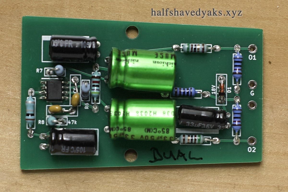
click to enlarge photo
Documentation in progress - in the meantime ask me if you have questions
email me at parenthetical at this domain
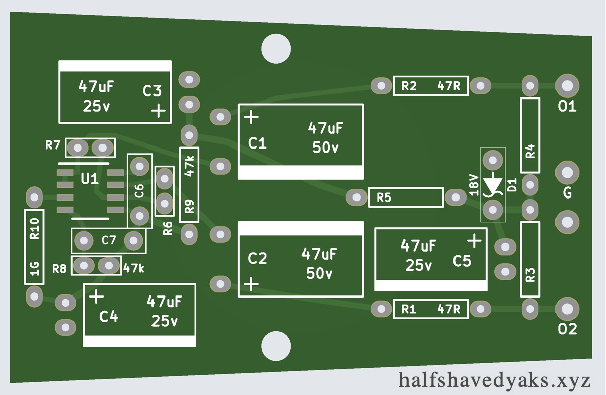
This board has an opamp-driven circuit on a board designed for cheap donor mics the BM700 and BM800.
This is my version of DJJules' dual opamp pcb here: True-Condenser-OPA-Mics
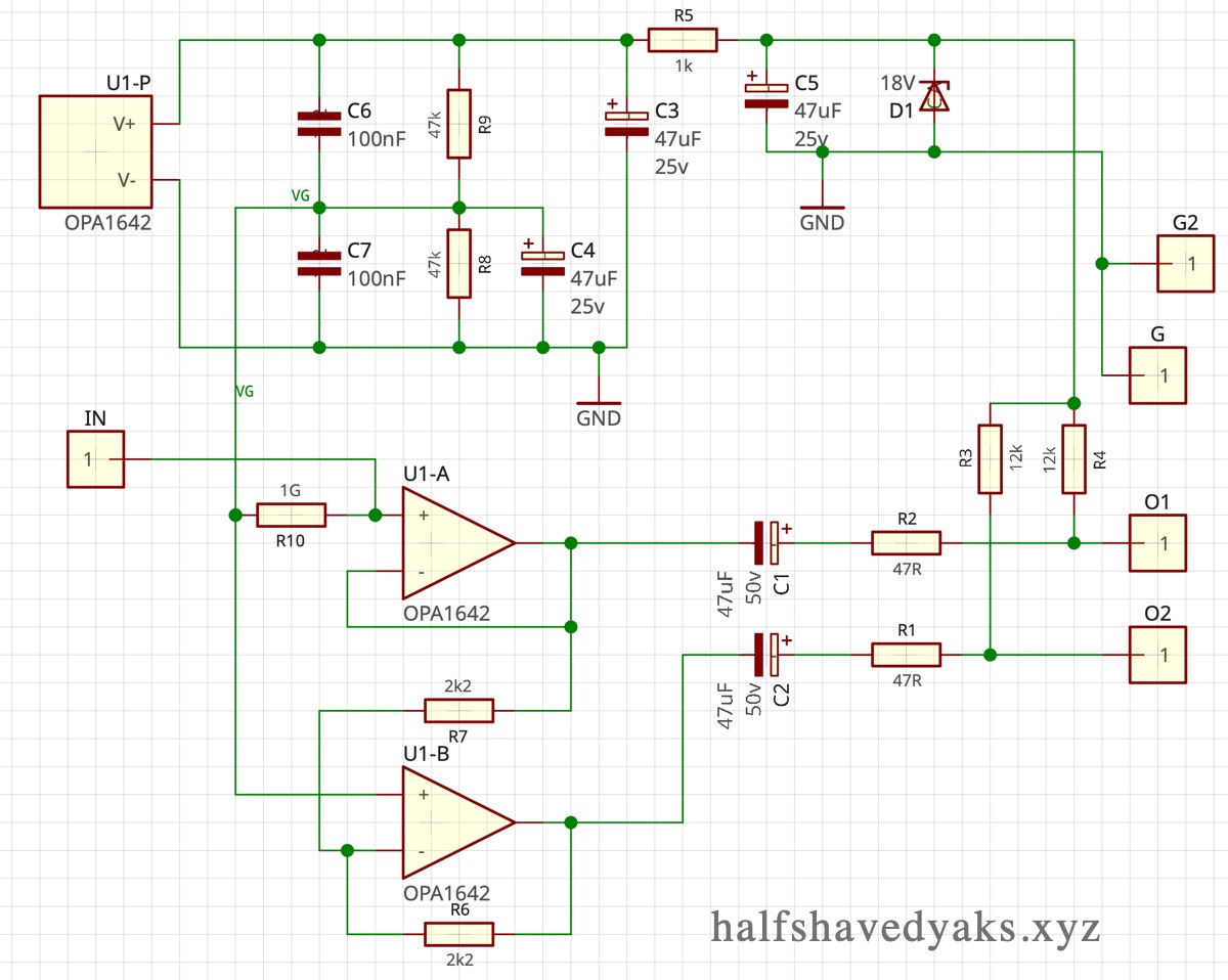
This circuit is a simple opamp mic headamp. It has 2 stages, and initial non-inverting buffer driving ones side and then an inverting buffer to drive the other balanced pin. It has a gain of 2 (6dB). This dual opamp version drives both pins 2 and 3 of the XLTR, but since there is an extra stage to create the inverted signal it has a very slightly worse signal to noise ratio than the single opamp version. This should not be noticeable in most real life uses.
The input terminal is pin 3 of the opamp where it joins the 1G resistor. The other side of the capsule should go to the polarisation voltage supply (for true condenser capsules) or to ground, (for electret capsules). This circuit is not intended for electret capsules with an internal fet.
I have used an OPA1642 this is a very good sounding low noise modern opamp with relatively low current requirements (1.8ma per side). The board is made with SOIC8 solder pads - so you can use any SOIC8 single fet input opamp - but if you use one with higher current requirements you may need to lower the values of R3 and R4. You'll also want an opamp with very low noise.
Z1 is a 18v zener on the schem, though I usually use 15v or even 13v. this gives loads of headroom, probably more than needed.
At time of writing (Aug 22) I have assembled this board but not yet tried it in a mic. However the single opamp version is tested and works great.