
A dual single ended opamp microphone circuit
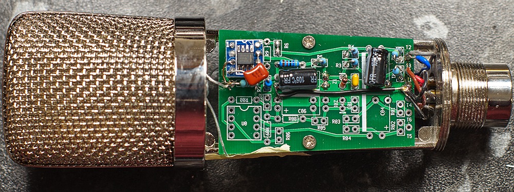
click to enlarge photo
Documentation in progress - in the meantime ask me if you have questions
email me at parenthetical at this domain
This board has two entirely separate opamp driven circuits on a board designed for cheap donor mics the BM700 and BM800.
This is my single opamp-per-channel redesign of DJJules' dual opamp pcb here: True-Condenser-OPA-Mics
Designed for use with a 5 pin XLR to give dual outputs for dual diaphragm capsules. But can be easily used as a single headamp by only populating one side of the board (like in the photo).
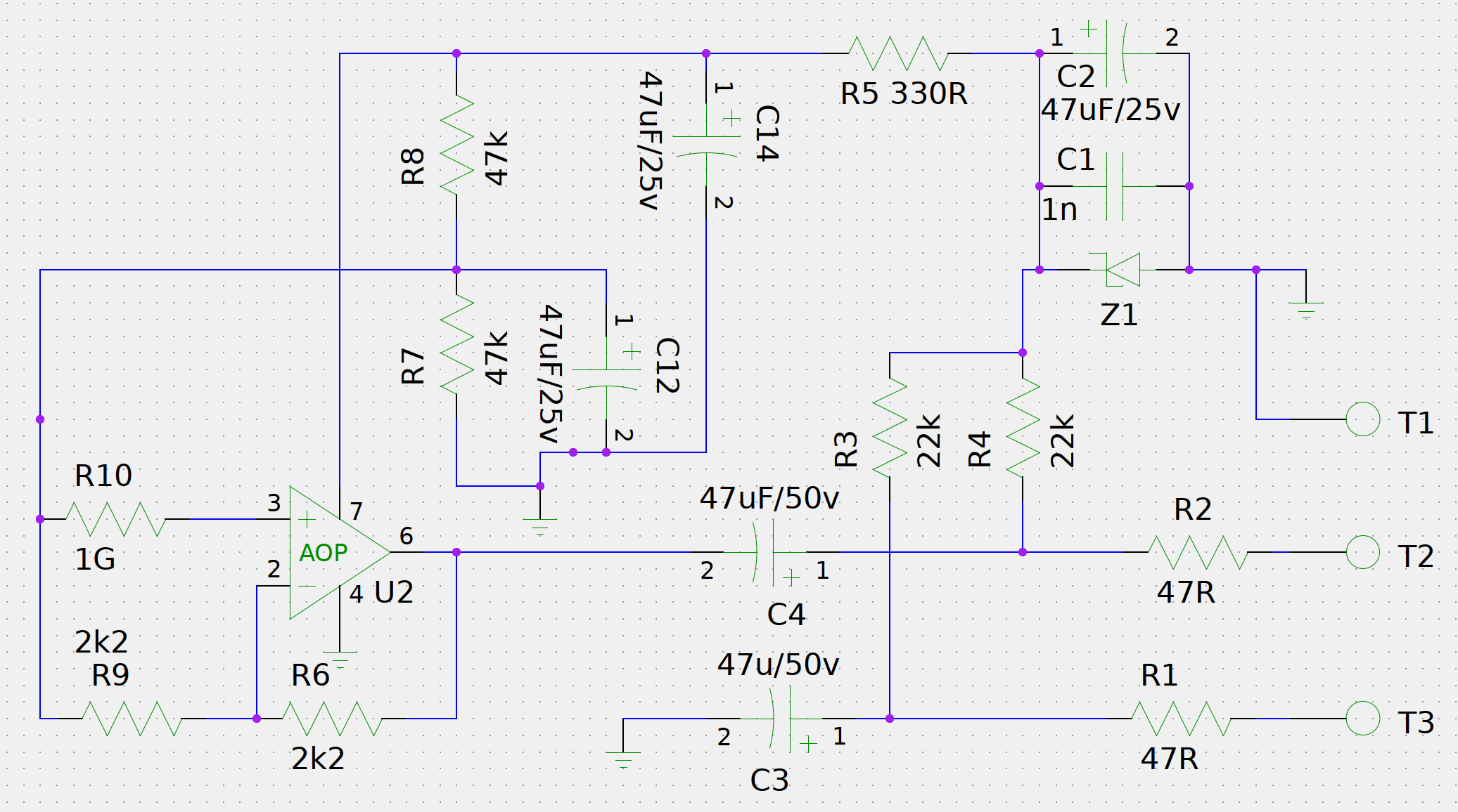
This circuit is a super simple single opamp mic headamp. It is really nothing but a single opamp - all the other components are just providing power to the opamp correctly, and impedance balancing the output and making connections.
This circuit uses a virtual ground setup for the opamp power as we only have a single power supply. I won't explain that here as there are loads of explanations on the net. Anyone who has built a battery powered fx pedal using an opamp will have come across this before.
The input terminal is not shown on this schematic (sorry), but it is pin 3 of the opamp where it joins the 1G resistor. The other side of the capsule should go to the polarisation voltage supply (for true condenser capsules) or to ground, (for electret capsules). This circuit is not intended for electret capsules with an internal fet.
I have used an OPA1641 (soldered to a DIP8 adapter as you can see) this is a very good sounding low noise modern opamp with relatively low current requirements (1.8ma). The board is made with a DIP8 socket - so you can use any single fet input opamp - but if you use one with higher current requirements you may need to lower the values of R3 and R4. You'll also want an opamp with very low noise.
Z1 is a 15v zener - this gives loads of headroom, probably more than needed. The voltage at the opamp positive power pin is 13.7V, so the opamp is running on +/- 6.8v.
As you can see from the photo, I have made the dip8 adapter so that the connection from the input pin of the opamp is soldered directly to the 1G resistor and the capsule wire without using the board trace. This is to minimise the risk of a dirty board and extra wiring length causing issues with the high impedance input. It may not be necessary if you keep the board clean - I was just experimenting with how easy it is to do (very).
The self noise of this circuit when using the low noise OPA1641 is about 1dB lower than the Schoeps circuit, when wired in unity gain. When configured with 2x gain as per the schematic the self noise is 5dB higher than the Schoeps. The Schoeps gain/sensitivity is approx 1dB less than this circuit in 2x mode and 4dB higher than this circuit in unity mode.
The upshot of all this is that this circuit has higher self noise than a Schoeps, relative to sensitivity, but that this difference is not noticeable in real life use as it is drowned out by ambient noise, and by the capsule self-noise. All these figures are approximate.
The gain can be set to the desired level using the ratio of R9 to R6 in the normal way for an opamp. The schematic shows R9/R6 values for for a total gain of 2 (+6dB) to match Jules' circuit or a Schoeps. However I have found this inconveniently high output for some of my mic preamps so I have built mine with a gain of 1 (unity), by omitting R9 and replacing R6 with a wire link.
I have added 1nF ceramic caps on the back of the board under the opamp from the power pins to virtual ground. On the schematic this is easiest described as across R7 and R8. These will be added to a future version of the board, but for now it is quite easy to solder them on the back. This is good practice for opamp power filtering but I'm not sure how essential it really is, given that I have high quality electrolytics fairly close to the opamp. Those extra caps probably make C1 unnecessary.
Note that some of the electrolytic caps are mounted on the back of the board. I use and recommend, in order of (very slight) preference, Panasonic FR, FM, and FC capacitors.
Based on quite limited use so far I like the sound of this circuit quite a lot, I may prefer it to the Schoeps circuit, although I haven't used it enough yet to be sure.