
Hybrid fet and transformer mic circuit
Board reference code HFT
questions? email me at parenthetical at this domain

Quick build notes
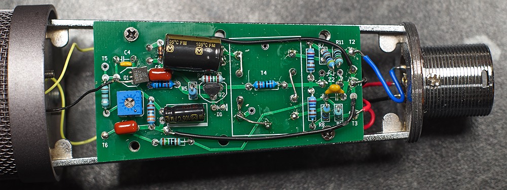
This board requires two ground wires - see the black wires installed in the photo. This give a low impedance star ground without disrupting the full coverage of the ground plane. Possibly obsessive overkill, but it does no harm.
This project is just as easy to build as the other ones on this website, but it can be a bit tricky to get biased just right. You'll need to actually understand the circuit. The biasing is discussed in the circuit description below and I will add more explanation as time allows.
It is highly advisable to make sure you understand the basic classic fet and transformer circuit described on my other page here., before attempting to understand or build this one.
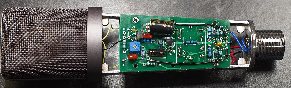
This board is designed for tapered mic bodies such as those sold on aliexpress as a "mini U87" however these vary in mounting holes and the mounting holes may or may not match up. This board fits the bodies with the finer grille like the grey one in the pics, but the holes don't match for the cheaper version with the coarser grillas seen in my other page here. The board should still fit in the version with the coarser grille it is just the mounting holes that don't match si improvisation may be required to get it mounted.
Circuit explanation. (work in progress)
I'm aiming to provide simple explanations of how each circuit works of a type suitable for beginners who can maybe build a kit, but don't really understand the circuit. The sort of explanation I wish I'd had when I started building DIY electronics. No doubt it will take a while to get these explanations as clear as they should be. Email me to suggest revisions or point out errors.
This circuit was inspired by at least 3 others: the classic Neumann fet circuits such as the KM84, the chinese condenser mics of the early 2000s, and Henry Spragen's Schoctava circuit.
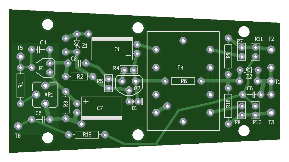
The circuit has three stages. The input fet stage, which provides voltage gain. The PNP transistor stage which provides current gain, or acts as impedance buffer if you prefer, and the transformer, which reduces the output level, while providing further output impedance reduction and adding some tonal colour.
Quick signal flow overview: Signal enters at T5, is amplified by Q1, leaves by the drain of Q1 and is AC coupled to the next stage by C8. Signal enters Q2 at the base, where it gains current, then flows through Q2 emitter, through C1 coupling cap, to T4 transformer, which reduces the level and lowers the impedance, it then leaves T4 as a balanced signal and leaves the mic through resistors R7 and R8.
Quick power flow overview: (conventional pos -> neg current direction): Power enters the mic at pins 2 and 3 from phantom power via the 6.8k resistors in the mic preamp, it then flows through R9 and R10 to C2 where it is stabilised for use by Q2. Power flows through Q2 from emitter to collector (PNP transistor) and is stabilised for use by the fet by C3. Note that this arrangement means that the fet is essentially running on the "exhaust" of the PNP transistor, we are using the same current twice, once in the PNP and once in the fet. Power then flows through R2 into the drain of the fet, then through the fet from drain to source, then through R3 to ground.
The input fet stage
T5 is connected to the capsule backplate, T6 is connected to the capsule diaphragm. (or these can be reversed depending on the polarisation scheme in use.) If a polarisation voltage board is used then T6 is unused and the PV board is used instead.
Signal enters at T5. It is amplified by the fet Q1 in a common source gain stage. The optional cap C4 creates negative feedback, reducing the gain and making the stage more linear. (This arrangement is sometimes called a charge amp) C4 can be left out, but you might find you have too much gain for the next stage in that case. Also I like the sound.
A voltage is developed across R3, and stabilised by C7, this lifts the source of the fet to a higher voltage than ground, leaving the gate referenced to a lower DC voltage for bias through R1. (fets require negative bias voltage at the gate). The amount of this bias voltage that is actually used to bias the fet is determined by VR1. VR1 can be any value significantly higher than R3, eg a 100k trimpot would do if that's what you have. Q1 is biased simply by adjusting the trimpot. A good rule of thumb bias point is to adjust so that the voltage across R2 and the voltage across the fet from drain to source are the same (in this case 10v each).
The output signal voltage is developed across R2, and the signal leaves the stage through C8 which AC couples / DC decouples it from the following stage. C8 is therefore a sound-quality-critical cap, and a quality film cap should be used. The value can be anything from 100nF to 1uF. Lower values than 100nF can be used if audible bass rolloff is desired. I usually use around 330nF Panasonic ECQV 50v stacked metal film caps. Wima FKP2/FKP3 are also good, but are larger and you may need to check the physical size.
Between 220n and 1uF the LF rollof point will be below 20hz, however there will be an effect on the relative phase of low frequencies, so oversizing this cap can lead to a more linear bass-to-mids phase relationship, and a subtle effect on tone.
The PNP emitter follower stage
Both transistors are running on the same current, in series from a power point of view. This can make biasing tricky since any change in the current drawn by one transistor will affect the other. The aim is to get both transistors drawing exactly 1ma with a drop of ~20v over each transistor and it's load resistor (Q1/R2 and Q2/R6). Z1 is inactive in normal operation, but protects C3 allowing a 35v cap to be used if desired, it also protects the fet from overvoltages.
Q2 is biased by adjusting the ratio of R5 and R4. Higher values of R5 will bias the transistor cooler using less current. As with Q1 the aim is to drop half the voltage across R6 and half across the transistor between emitter and collector, in this case 10v each. In future revisions I may use a trimpot in place of R5.
D1 protects Q2 from overvoltages and reverse voltages in fault situations. The delicate BE junction of Q2 could also be protected directly if desired by adding a 1N4148 diode in parallel with R4, with the positive (stripe) side towards the emitter of Q2. I may add a dedicated spot for this in a future revision.
The transformer and output
Transformer is intended to be a Vigortronix VTX-101-002 2:1 ratio. Or the OEP equivalent which is identical. (In my build I actually used a VTX-101-003 wired as 3.2:1 ratio, just because I didn't have a spare of the 2:1)
Better (and much more expensive) transformers such as the excellent Lundahl LL1538 (or the less common LL1935) also work very well in this circuit, but this board does not accomodate them. If people ask me for a Lundahl version of the board I will make one.
The polarisation voltage
The polarisation voltage is derived from the phantom power with two filters using 10M resistors and 220nF capacitors. I use a ceramic for the first filter and a quality film cap for the final filter. Cap values are not critical but they must be at least 50v rating. If the caps are too large the polarisation voltage will take too long to get up to voltage.
A matching polarisation generator board (see pic above - link coming soon) is also available to give both positive and negative 60v polarisation voltages. The higher voltage causes higher output and better signal to noise ratio, and the provision of a the negative voltage allows switched multipattern operation.
There are 3 or maybe 4 distinct different circuits that can be built using this board, with or without a transformer, if you don't mind departing from the outlines on the silkscreen