The classic fet and transformer circuit
Board reference code CFT
Page about the classic transfomer boards
Documentation in progress - email me if you have questions or if you see errors.
email me at parenthetical at this domain
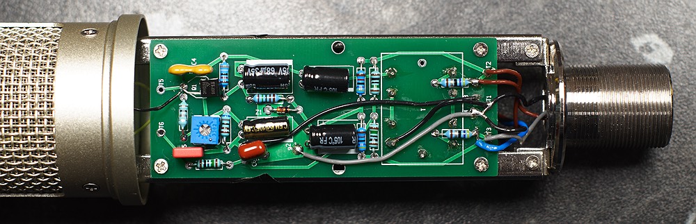
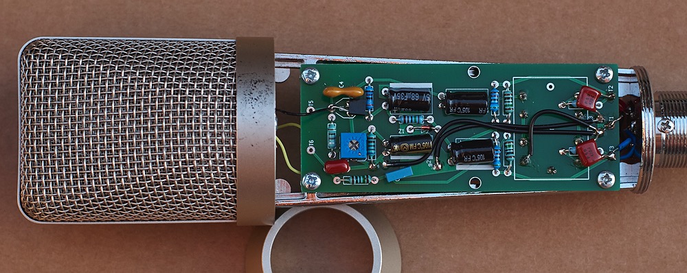
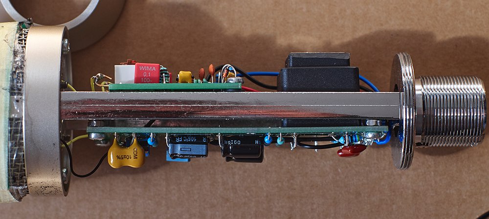
This board is a classic Neumann-like single fet with a transformer circuit. It fits in two different Chinese donor bodies. The cylindrical one above and the tapered one below. The tapered one is a tricky fit though, more on this below in the build guide.
I'm aiming to provide simple explanations of how each circuit works of a type suitable for beginners who can maybe build a kit, but don't really understand the circuit. The sort of explanation I wish I'd had when I started building DIY electronics. No doubt it will take a while to get these explanations as clear as they should be. Email me to suggest revisions or point out errors.
Quick Links
Circuit Description and Explanation
Overview and Design Approach (work in progress)
This is basically a KM84 circuit. A great many classic and DIY mics have used variants of the this basic approach.
Designing a mic circuit to run from phantom power could be seen as challenging, because there is not much current available. However there is loads of voltage. Phantom power is high voltage but low current. This was originally to allow capsule polarisation directly from the phantom power source, but it presents a challenge for making a good impedance converter headamp where we would normally prefer more current at lower voltage.
This circuit is a very elegant and simple approach to this situation. It is the same sort of design commonly seen in valve equipment, and in fact the earliest mics that used this topology used valves, and the fet was simply a later substitute.
Rather than try to create a low impedance output directly, as one might do in a modern design, the fet produces voltage gain, at a relatively high impedance. This results in an excessively high voltage signal, but at low current. The transformer then converts the high voltage low current signal to a low voltage high current (or at least low impedance) one, which is what we want at the output.
This uses the high available voltage efficiently, while keeping current consumption very low. This design won't strain your phantom supply as it draws less than 0.5ma as shown.
From a pure engineering perspective, this has two major downsides. The first is that the gain stage and transformer both create more harmonic distortion than a solid state impedance converter such as a source follower. The second is that the transformer is bulky, heavy, and expensive.
Nevertheless, the distortions created are musical sounding and are an essential part of the desirable sound of this sort of mic. It isn't as accurate as it might be, but it does sound nice. So this circuit is suitable for mics where you want the mic to enhance the sound, rather than simply capture it. It is more suitable for close-micing single instruments and voices than distance micing of complex ensembles, though depending on the capsule and the situation it can be good for the latter as well.
Circuit Description. (work in progress)
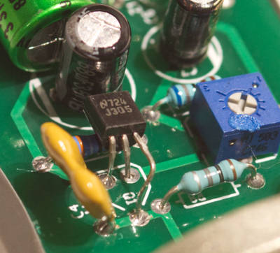
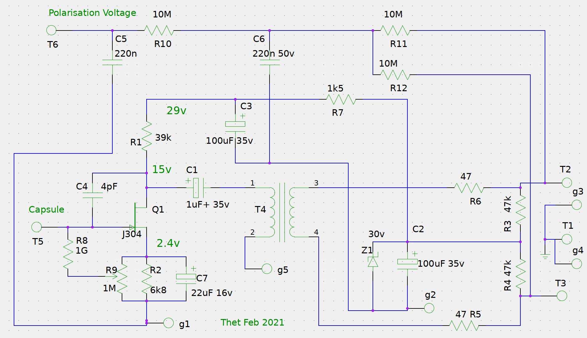
The N channel fet is configured as a common source voltage gain stage. Also known as a drain follower. It is basically the same as a valve gain stage. Signal is applied at T5 to the gate of the fet. Power flows from drain to source (if imagining as conventional current flow positive to negative).
These jfets are depletion mode devices, which means they require that the gate voltage is negative relative to the source voltage to put the fet into the correct operating area. This is achieved by raising the voltage at the source using R2, and referencing the gate to ground using R8. R8 is bypassed with C7 to keep this voltage stable DC and unaffected by signal. This point at the source of the fet can be regarded as ground from the point of view of the amplifier, actual ground becomes just a negative bias voltage in this way of looking at things. Hence the term common source, since the source of the fet is at the common, or ground potential.
Since the fet uses very little current a low IDSS fet is fine in this circuit. I like J305.
The lower the gate voltage the less the fet conducts and the higher the gate voltage the more the fet conducts. The quiescent operating point, or bias voltage, should be set so that the drain of the fet is halfway between the supply voltage at C3 and the source voltage of the fet. This is achieved by changing the reference voltage at the ground side of R8 by adjusting the trimpot R9. The signal causes the conductivity of the fet to change proportionately, by biasing the fet in the middle of the available voltage we ensure that the signal has room to swing equally both ways. (This is a beginner explanation, there are subtleties that I'm glossing over.)
As the conductivity of the fet varies with signal, so the voltage across R1 is caused to vary. This creates the output voltage, by modulating the power supply voltage. So the drain of the fet becomes the signal output terminal. (Hence the term drain follower, as the output follows the voltage at the drain). Larger values of R1 will cause greater signal swing. In this circuit we want a high gain, so we have used a fairly high value of 39k. Values can be between 10k and 47k.
If the Trimpot R9 is turned all the way down and the fet is still running too hot, then the value of R2 should be increased. Similarly if R9 is adjusted near the top of its range to achieve correct bias, then R2 can be decreased. The given value of R2 is an estimate, since fet characteristics vary a lot.
The optional cap C4 creates negative feedback, reducing the gain and making the stage more linear. (This arrangement is sometimes called a charge amp). Larger values have a greater effect. The potentially useful range of values is 0 to 15pF. C4 can be left out (0pF) for higher output and more distortion. Higher values may be useful for more SPL handling and less sensitivity, if that is required.
The signal at the drain of the fet is coupled to the transformer through C1. The quality of this cap is important for sound quality. Traditionally a 1uF or so high quality film cap would be used. I find I also get good results with high quality electrolytic caps. When using electrolytic caps larger values seem to sound better, you can go as high as 100uF if you like. Panasonic FR or FM caps have a rich but crisp sound, Nichicon Muse are more restrained and clear but a little dull (probably lower distortion), and good quality film caps are very clear and clean, but the smaller values of 1uf or so may cause some phase shift in the low frequencies. I like Panasonic ECQV film caps (now hard to find) or Wima FKF2 or FKP3 (bulky, may be hard to fit).
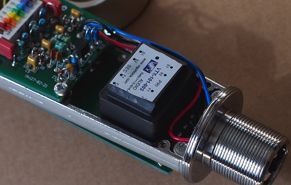
Transformer is a Vigortronix VTX-101-003 6.45:1 ratio. Or the OEP equivalent A262A3E which is identical. It is wired in it's native ratio of 6.45:1. It could also be used in the 12.9:1 ratio, but i haven't tried this.
Better (and much, much, more expensive) transformers such as the superb Lundahl LL1538 (or the less common LL1935) also work very well in this circuit, however this board does not accomodate them. If there is demand for a Lundahl version of the board I will make one.
Power to the fet is filtered with a 2 stage filter. Stage 1 is formed by R4/R5 and C2, stage 2 is formed by R7 and C3. C2 and C3 are probably larger than needed on the schem, 47uF should do fine. Z1 protects against overvoltage and allows the use of 35v caps. Z1 is inactive at normal operating voltages. If 50v caps are used for C2 and C3 then Z1 can be omitted.
The Polarisation Voltage
The polarisation voltage is derived from the phantom power with two filters using 10M resistors and 220nF capacitors. I use a ceramic C0G type for the first filter (C6) and a quality film cap for the final filter (C5), however I'm not sure that is necessary. Cap values are not critical but they must be at least 50v rating. If the caps are too large the polarisation voltage will take too long to get up to voltage.
A polarisation generator board is also available to give both positive and negative 60v polarisation voltages. The higher voltage causes higher output and better signal to noise ratio, and the provision of a the negative voltage allows switched multipattern operation.
If a polarisation voltage board is used then T6 is unused and the PV board is used instead. In this case C5, C6, R10, R11 and R12 can be omitted.